
Warping the mirrors of an extremely large telescope on Earth
Credit – TMT International Observatory
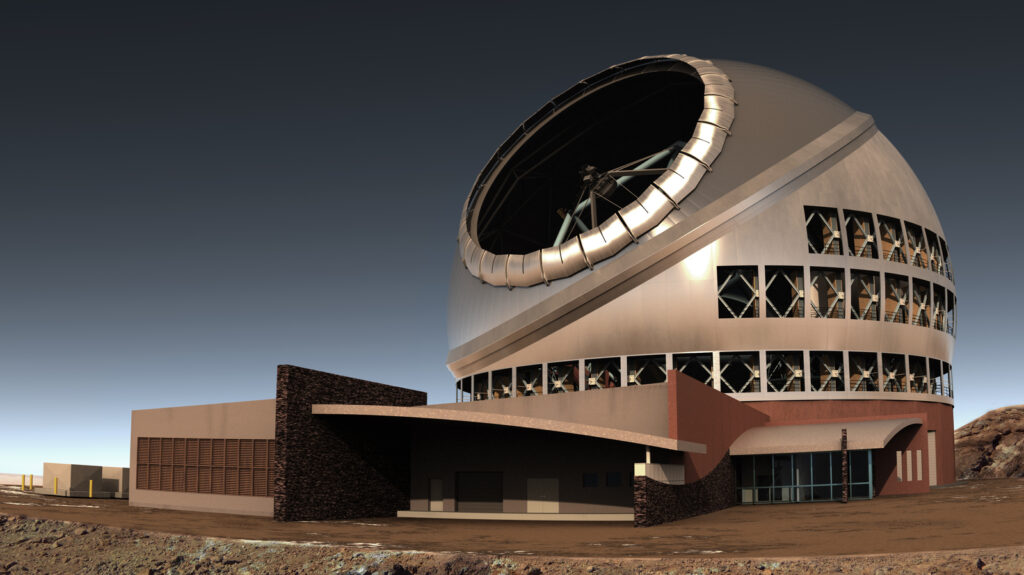
Although the mirror segments of the new Thirty Meter Telescope (TMT) are manufactured to an extremely high level of precision, during operation they may still need to be dynamically warped to correct small optical aberrations, such as those caused by environmental disturbances. In collaboration with TNO and S&T, Technolution Advance is taking up the challenge of developing the control electronics for testing and validating the TMT mirror segment support assemblies.
The Thirty Meter Telescope (TMT) is a new class of extremely large telescopes that will allow us to see deeper into space and observe cosmic objects with unprecedented sensitivity. With a total light-collecting area of 655 square meters, aided by state-of-the-art adaptive optics technology to correct for atmospheric circumstances at first light, it will be able to produce images of the universe at a resolution that’s an impressive twelve times higher than that of the Hubble Space Telescope.
The TMT’s hyperboloid primary mirror will consist of 492 separate, hexagonal mirror segments of reflective glass. Each segment will be mounted on its own segment support assembly (SSA) that holds the segment in. Every SSA incorporates a warping harness system capable of changing the optical figure of the mirror segment.
Each warping harness employs 21 motor actuators that use leaf springs to exert just enough force on the mirror to compensate for the optical aberrations. In addition, the harness has 27 strain gauges, one for each point where the mirror is in contact with the support structure. The forces measured by these 27 sensors can be used to model the optical influence the actuators will have on the mirror segment, and confirm that the support structure is operating correctly.
Before integrating an SSA with a mirror segment, an SSA test system is used to confirm that the SSA is functioning properly. Technolution Advance has been tasked with designing the control electronics for the SSA test system. This system will analyze and process the strain gauge measurements and control the motor actuators on the warping harness. The control electronics will be divided across three enclosures around the SSA test system.
Requirements
The TMT is being developed by TMT International Observatory (TIO), a non-profit organization that joins together scientific institutes from across the world. It quickly became clear during the initial talks with TIO and our partners TNO and S&T that the specifications for the warping harness controllers needed further research and clarification. Obviously, any electronic system designed to perform advanced metrology and control in such a complex and delicate environment has to satisfy many well-defined requirements. However, when all of the requirements are specified at the upper limits of what’s technically possible, there’s a risk that the working solution isn’t fully optimized. In a scientific context such as the TMT (or in any complex systems engineering situation), the desire to attain optimal or even perfect physical and electronic properties for the end results must always be weighed against the practical implications.
The controllers for the TMT’s SSA test system are subject to many very specific requirements, for instance in the area of heat management. For the deformation measurements, high precision is needed to control the mirror shape. For the SSA test system, the accuracy of the deformation measurements must at least match the operational accuracy. Another question is how the strain gauges can actually be read out with the least disturbance, and how these measurements relate exactly to the required motor actuator movements.
All these issues, and many more, will need to be addressed. In any complex systems engineering project, all parties involved need to have a clear view of the required components, their specifications and requirements, the connections and interfaces between components and who’s responsible for the development of which part of the system. One thing never changes: there are great challenges for every component. This is why, in many cases, it’s not possible to have finalized requirements and specifications at the start of the project.
Metrology solutions
An open dialogue and a constructive approach will help us translate TIO’s ambitious needs into feasible specifications, and eventually into a valuable system that will produce the expected results. We believe that the process of converting guiding principles into concrete specifications is a crucial element of systems engineering in complex development environments. At Technolution Advance, we employed it successfully for the data acquisition engine of the Fast-EM multi-beam scanning electron microscope and the control system of Nearfield Instruments’ innovative atomic force microscopy scanner for semiconductors. Two comparable, more recent projects are a control and data processing unit for microsatellites and test equipment for optical and electrical testing of photonic integrated circuits. These are all multi-partner, complex systems engineering projects that deal with highly sophisticated metrology challenges.
The TMT is a unique and interesting project for us in that it deals at the same time with microns and lightyears. Just like in any other scientific endeavor, scientists like to design the telescope with ideal dimensions and specifications. For us as technical engineers, the challenge is always to keep our feet firmly on the ground and deliver a system that lives up to those high expectations, without losing sight of the practical implications of every decision that’s made. The basic principles of systems engineering are a great help in reaching that goal. Good communication between all partners may be even more important.
Controlling the warping harness
Controlling actuators while performing an accurate and reproducible measurement within the same device means engaging in a challenging act of balancing interests. While thermal and electrical stability are required for accurate and reproducible measurements, controlling the actuators generates heat and electrical disturbances that may interfere with the surrounding electronics and thus with the measurements.
Strain gauges are typically read out in a bridge configuration with a very small differential output signal. Voltage variations on the strain gauge bridge caused by the controlling of the actuators will become visible in the measurements and should therefore be avoided as much as possible. This so-called “common-mode rejection ratio” (seen from the differential measurement input) is a measure for the measurement device’s sensitivity to power supply disturbances.
To achieve maximum precision, the actuators in the control boxes are moved to new, stable positions before a measurement in the TMT validation module is performed, eliminating the need to actuate them during the measurement process. This also limits energy dissipation in the control box, thereby reducing the heating up of the device and the thermal drift of the measurement electronics.
Using a generalized command control interface, the validation application controls the movement of the actuators to new positions and determines the measuring moments. The warping harness controller typically uses a chain of three control boxes to enable control of a total of 21 actuators from a central test setup.